 |
Datalogger DL01 |
|||||||
|
|||||||
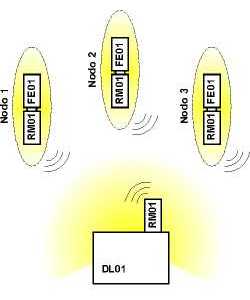
The DL01 unit is a high performance datalogger, designed to operate in a wireless network. The datalogger communicates with one or more measurement nodes, equipped with appropriate sensors. Each device has a radio modem operating according to the ZigBee standard; the communication takes place via a star network in which DL01 is its center. The sensor data are sent from the measurement nodes to the datalogger and recorded on its non-volatile memory. At any time the data can be collected from DL01 to a PC using a standard USB interface. Depending on the type of measurement, the network can use different types of radio modems (RM01, RM01-P) which are interchangeable and differs only for RF power transmission. Each modem is individually powered by a rechargeable internal battery. The autonomy depends on the sampling frequency of the node and can allow up to several months of continuous operation. Recharging the battery takes a few hours by placing the radio module in any of the slots provided for the datalogger (DOCK0, 1, 2); you can charge simultaneously up to 3 batteries. Thanks to the wireless communication is possible to perform measurements of various physical quantities providing galvanic isolation and avoiding any issue concerning ground loops. The sample time of the data transmitted by a measurement node can be selected in a range of 1...65365 s). Each node consists of a radio modem and a signal conditioning device (FE01 or FE02 family) which are connected physically to the measuring sensors. In addition to the wireless nodes, DL01 can support simultaneously devices communicating via RS485 serial thereby increasing the versatility of the system. There are various FE0x models; everyone can manage one or more independent channels allowing for the measurement of physical quantities of different kinds. The datalogger automatically recognizes the type and magnitude of measurement, and it does not require any manual operation. You can add up to 30 measurement nodes to the network.
|
|||||||
Key Features |
|||||||
|
|||||||
Example of datalogger setup |
|||||||
 |
The figure on the left shows an example of a wireless network managed by a DL01 datalogger with three measurement nodes. |
||||||
Advanced performances |
|||||||
Some FE0x devices need to be connected to the datalogger permanently via RS485 serial interface. In this case it is requested to insert in DOCK2 of datalogger the INT11 interface adapter (more details on FE03/04 description). When an application requires a prolonged recording session (e.g. in-situ transmittance measurements) may be interesting to access the datalogger with a GSM remote connection. This possibility is provided by the DL02 datalogger.
|
|||||||
|
|||||||
|
|||||||