| ThermoZig |
||||
In-situ measurement of thermal transmittance of building elements
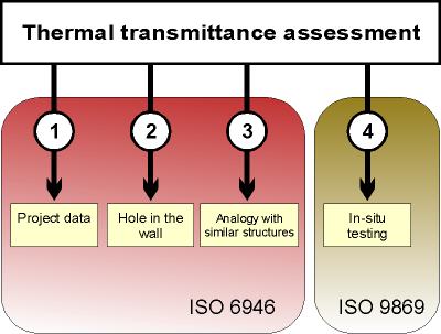
In order to estimate the energy requirements and subsequent emissions of CO2 for winter heating or summer cooling of a building, it is important to determine the thermal transmittance values of its envelope. The evaluation of the thermal transmittance (U-value) can generally be conducted according to one of the following 4 different scenarios: 1) The stratigraphy of the structure is known (thickness and type of materials of the walls are known with certainty); the transmittance can be calculated in accordance with ISO 6946. 2) The stratigraphy is not known. A hole can be drilled to determine the type of material and thickness. The hole may be small in size and structure can be examined with an endoscope or coring can be performed with an external examination stratigraphy. The experience of the practitioner plays a key role. Once the stratigraphy of the wall has been determined, the transmittance is calculated in accordance with EN ISO 6946. 3) The building is attributable to a particular building types and features that are well known. It is possible to act by analogy estimating the transmittance of the components. 4) The transmittance of the structure is measured in-situ in accordance with ISO 9869. The following diagram summarizes the different strategies:
The acquisition of data for the energy diagnosis of an existing building or for the testing of a new construction often involves considerable difficulties due to unavailability of the project drawings and non-correspondence of these with the built; for this reason it becomes very important to have in-situ measuring instruments. Additional benefit of the instrumental measurement is the greater correspondence with the actual values. From the field experience it was found that generally the values of transmittance measured are higher than the calculated values (even up to 20-30%). The reasons for this difference to be found among: The in-situ measurement with the use of a heat flow meter (HFM) provides generally good results; the data reported by the practice indicate an average value of the error less than 8% -10%. Typical configuration of the sensors consists of a flow sensor to be positioned on the interior surface of the building element under test and by two or more temperature sensors to be positioned both on the interior surface and the exterior surface. The use of more temperature sensors allows averaging the values, decreasing the error in case of elements not sufficiently uniform. The following figure shows schematically a typical sensor installation:
In case of steady state thermal conditions, Lambda and U may be derived experimentally simply through the instantaneous measurement of the heat flow and indoor and outdoor temperatures. The measurement procedures adopted in the field must therefore provide for an appropriate processing of measured data in order to manage properly the transient effects (accumulation and release of thermal energy) induced in the wall by the variable thermal conditions.
In practice it is easier and more reliable to measure the temperature of the surfaces (Tsi and Tse) and calculating the thermal conductance. Then the thermal transmittance can be derived by the conductance using the internal and external adduction coefficients (hi and he) in accordance with ISO 6946.
Ucalc program
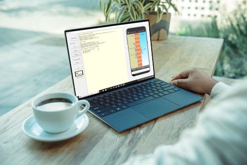
Ucalc is a plug-in program that can be run directly from the datalogger manager program (Dataget). With Ucalc you can calculate the thermal transmittance of a wall in-situ and prepare a report containing data and graphs in PDF format. The calculations are based on the average method suggested by ISO 9869. The program works on any version of Windows, starting from Windows XP and up to Windows 10.
 |
||||
Ucalc allows you to display figures and graphics of the elaboration results. At the end you can save a complete report in PDF format.  |
||||
The advantages of a wireless measurement system
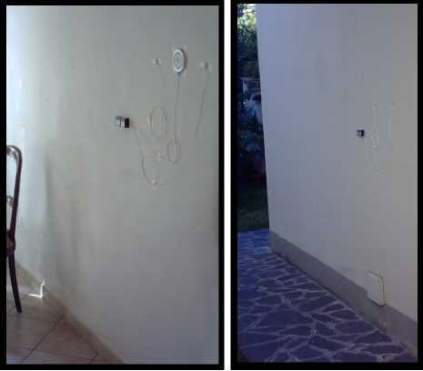
The physical quantities to be monitored for the measurement of the transmittance are the temperature and the thermal flux. The minimal setup provides for the detection of the surface temperatures of the inner and outer wall of at least two distinct points and the measurement of the thermal flux passing through the same. The following pictures shows a solution to meet these needs:
|
||||
 |
||||
INDOOR |
OUTDOOR | |||
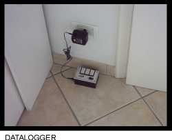
The installation of the sensors and measurement nodes is facilitated by the wireless connection, it was not necessary to drill the wall or use complex cables layout. Thanks to the ZigBee protocol, the autonomy of measurement nodes is very high. For applications of this type, the internal battery to the radio modem is capable of powering the measurement node even for several months. The battery is also of the rechargeable type and can be completely restored within a couple of hours. The choice of the location of the datalogger does not pose particular problems. In this case it has been positioned inside the dwelling in a way to not become a significant hindrance to the normal household activity.
In this example has been taken into consideration only one wall and were used only two measurement nodes. It is interesting to note that the datalogger is able to manage without any modification many other measurement nodes. This opens the field to the ability to perform multiple simultaneous measurements by simply adding more nodes on the walls. With a multiple simultaneous measurement you can monitor a complete building in a single recording session. FE01/02 devices with two heat flow or more temperature sensors (4 or 8) can be used when more accurate measurements are needed, especially if the walls are not very homogeneous.
|
||||
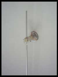
The picture on the right shows another method of installation of the thermal flow sensor. Through the metallic structure, the sensor is pressed against the wall so as to ensure a good thermal contact. This type of application has the advantage of allowing the measurement and the removal of the device without damaging the plaster of the wall. |
 |
|||
Quick learning
Particular care has been taken to simplify the use of the system. Despite the versatility of the instrument, with a single button you can manage all phases of the measure in the field. The quick start guide that comes with the user manual covers all the basic operations
|
||||
| References | ||||
|
|
||||
| Standard configurations | ||||
ThermoZig
ThermoZig system is typically supplied for a single measuring point (2 nodes), any additional measuring points can be purchased separately. The system can handle up to 15 measuring points (30 nodes). |
||||
 |
||||
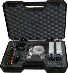
ThermoZig includes:
|
||||
|
||||
ThermoZig LT
Thermozig LT system is the most economical system for measurement of transmittance in-situ. It differs from Thermozig standard for the presence of a single wired node. This configuration allows you to approach the world of professional thermofluximeters at very low cost without any compromise in the quality of the measurement sensors. Thermozig LT can however be upgraded to standard version at anytime by buying separately the missing parts (3 radio modems and an additional FE01/02).
|
||||
|
||||
ThermoZig LT includes:
|
||||
ThermoZig BLE
ThermoZig BLE system represents the latest evolution of ThermoZig heat flux meters and is characterized by the addition of Bluetooth Low Energy support through which it can be managed remotely from a smartphone. ThermoZig BLE is typically supplied for a single measuring point (2 nodes), any additional measuring points can be purchased separately. |
||||
|
||||
ThermoZig includes:
|
||||
|
||||
| Bluetooth remote control | ||||
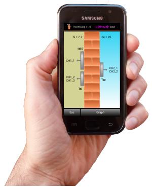
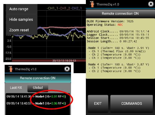
For devices based on Android it is now available ThermoZig app. This app allows you to connect to ThermozZig BLE via Bluetooth and use the following functions: - Monitoring of the battery level and the radio signal level received from each node in the measurement network. - Displaying of all channel signals acquired by the system (numerical and graphical format). - Estimate of the thermal transmittance in real time.
|
||||
 |
||||
| Internet remote control | ||||
The duration of a measurement of in-situ transmittance can be particularly extensive, especially in the presence of building elements of considerable thermal mass. When the test is conducted in sites not easily accessible, can be useful to have a remote connection that allows to download the partial data of the measurement in order to check the progress and determine when the session can be considered concluded. ThermoZig BLE can be provided with an Internet connection through which the entire process of measuring up to the drafting of the final report, can be controlled remotely from your office.
|
||||
 |
||
|
||